Getting there:

C8BEBDC0-11EC-4803-BC70-0402F4B528F5.jpeg


81599D1B-BBD9-4AA5-A395-8D4F3A45F44A.jpeg


Starting to look like something now.

Tomorrow, some more tig welding, fit the hinge assembly, start building the “glove box” portion and then on to final fit/finish and paint.

For the latch, I’m just going to go simple: a button on the top of the “lid” attached to a small “hook”. Press the button and the hook will release and allow you to open the door. A couple small tethers will keep the door from swinging down too far and hitting the existing dash plastics.

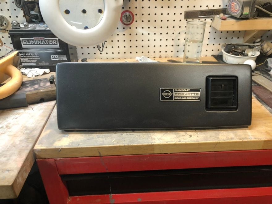
I grabbed a “corvette/chevrolet/built in BG KY” :

759822B4-99E5-4A13-B3AC-28E191D95076.jpeg


thats goes under the hood off ebay and I plan to “french” it into the door piece. I’ll give it a nice polish and a shot of fresh gloss black to spiff it up a bit. Should give it a little bit of oem “character“ without being too overbearing....

:)
 
Last edited:
  • Like
Reactions: YFCvii and RockyPM
Mr postman brought me a present today:

F10B58E7-2FD0-4896-848F-FE9B30636DE3.jpeg

Those are jammy!

;)

A little black paint, a little polish and those will look bangin’ on my old L98! A nice taste of corvette history to add more “flavor” to my C4.

The center bolt adapters are supposed to show up today (courier, not post) as well as the roller rockers I ordered.
 
Little closer every day:

A7D07371-3350-4820-AADC-F0581C402DB3.jpeg

C8E588CC-9AC4-488D-B080-762C5DF7780D.jpeg

B4A2A103-50D8-4C2F-8881-2968ED58B707.jpeg

Please ignore how raw and unfinished it looks. Right now I’m focused on getting it to the basic shape, the structure and proper functioning.

Once I get the raw construction done, it will be time for filler and final shaping. Then into paint.

And, now that I’m getting my TIG skills somewhat in order, I can fill any divots or voids if needed.

Next up will be teaching myself to tig cast aluminum so I can start porting and building my “Ultimate TPI”....lol!
 
Sat with an old friend today:

09EE2E76-BE8B-4317-94D0-6276B2F08CA2.jpeg

Coffee for me, battery charger for my friend.

My tuning software/hardware ahowed up from Moates yesterday:


666B2083-1B87-405F-9C30-2507F1102B9D.jpeg


Realtime tuning, datalogging, emulation and a “switchable” option that lets me load up 9 different calibrations. One for cruising, one for mpg, one for power with mufflers, one for power with cut outs, one for “valet”, etc, etc.

Will also make it possible to do things like program out the 9th injector, vats or any other parameter I don’t (or do) want.

The APU1’s capabilities will be essential once I get the “mega-TPI” built and/or the LT1 intake conversion...
 
Tried swapping on a valve cover today to see what it would look like.

Almost immediately, I was reminded of the reasons I hate GM’s so much. Damned near had to tear the whole top of the engine off just to change a valve cover.

Grrrrrrr. Stupid design.

GM may be able to build a nice, fast car that corners, but gawd help anyone who tries to wrench on it. Its like the eff-ing design engineers didn’t put a half an ounce of thought into servicing the damned thing.

I do know one thing now: as much as I like the “period correct” looks of that TPI intake, it’s coming off for the LT1 intake. Much easier to service things with the intake not being a maze of overlapping pipes and wires...
 
Last edited:
  • Like
Reactions: AlbertaZ06
Quick preview of the “corvette” script valve covers:

D3CF9520-1590-4224-B5D6-721D073D60DB.jpeg


Of course, they still need to be fully polished and the “orange” areas will be sprayed black, but those are going to looked damned good in there!

I started welding up the lt1 intake today. Had to stop as my 3/32 tungsten is just blowing away at 250 amps. I need to pick up some 1/8 tungstens and some 1/8” collets so I can hit it as hard as I can. Cast Al on the intake pieces is thick as heck and takes a full 250 amps to start the puddle without melting down the whole intake...
 
First pass making the L98/LT1 crossbreed intake:

36B85681-23D4-4C4A-AD5F-0C2D9366E5A8.jpeg


Ugly, but structurally sound. Making it pretty will come after I'm done modifying it.

Technically, I could finish up the welding and bolt it on like it is. But it would require things like coolant hoses and a remote thermostat. I'm going to actually cut the front off like I did the back and weld on the coolant crossover piece along with the thermostat housing. That will also allow me to raise the TB mounting pad and position it like it is in the L98 setup. That will pretty much turn it into a "drop in" piece. I'm currently considering raising the plenum roof when I cut the TB mount pad off in order to give the plenum more volume.

Essentially, the only thing that will be left of the LT1 intake is the center section with the runners, injector ports and plenum.

While it will take away some of the L98 low end torque "peaky-ness", it should also add Hp and extend the rpm range up into the 5500-6000 rpm range (instead of going flat at around 45-48,00RPM). The L98 bottom/mid range is fun, but you really can't get it all to the ground without blowing away the rear tires. Making it a little bit "softer" on the bottom end will help with launching hard, as it won't be as easy to blow away the tires.

After this, it's the roller rockers, a cam and then some datalogging/tuning. I'm shooting for somewhere round 300-350 crank. I'd like to push 40 hp crank, but that's another 150 hp over stock and it's extremely unlikley I'll get there with only the changes I'm going to make. No sense going for more than that as it's only going to get expensive (and tempermental) to push the gen 1 SBC past that point. If I ever want more than that, I'll have to look at maybe doing an LSx swap....


:)
 
Last edited:
Moving along:

D407A0BB-22B6-4CD2-A56A-AE85AE90F0C3.jpeg

AEF748CB-F7BB-4F0E-9F3D-97C21F70AAFB.jpeg

With the rear well on its way, I moved to doing the front.

what you see is the lt1 intake with the front removed to the injector bungs, the crossover/thermostat housing from an old L98 and the throttle body mounting pad bolted to the jig where the L98 TB mount pad would be.

This will give me the thermostat mounting like the L98 manifold and it will place the TB where it was meant to be in an L98 car.

I’m also raising the roof on the lt1 intake part (more volume and more options to blend the TB pad to the rest of the intake) and might even build a distributor cover plate, similar to how an L98 covers the distributor. Jury is still out on that one though..
 
The door in it's first coat of paint:


fr_4440_size880_e2acafc0fafc82b5a9e9758fc530b448a9decf04.jpg


It's not perfect by any means, but that's fairly decent for first coat. It needs to be allowed to cure for about a month now, then a good wet sand to smooth it out more and another coat of paint.

Should look pretty good!

Now to get the dash "plate" it attaches to fille dand painted.....
 
a little more work on the intake:

fr_4442_size880.jpg


fr_4441_size880.jpg


So, the L98 upper is juuuust a bit too wide to mate up to the opening in the top of the LT1 manifold. So I had to cut the sides in a little bit. It's still a touch too wide, but I can just "step it" in a bit to mate to the upper to the lower. The LT1 fuel rail mounting also necessitated the "step" in order to be able to insert and tighten the rail mounting bolts.

The good thing is the upper plenum egr and vacuum passages line up pretty good with the passages in the LT1 intake. I'll still have to rebuild the passages between the two, but it's looking to be a simple TIG in a couple tubes to "pass the gas" and call it done. then it's just a matter of TIG-ing the EGR to the back of the intake and fill in the remaining openings.

I'm considering reworking the sensor area at the front where all the L98 sensors plug in. Right now it's standing pretty tall and it doesn't exactly look nice. I may look to see if I can cut it down by half, for looks as much as anything else.

For the rear, I'll have to see if I can dig up an aluminum distributor cover so I can rework it to fit this intake. I've got a plastic one and an aluminum one, but the plastic is pretty much useless (for reworking) and the aluminum one is on the original L98 intake.

One of the good things about this setup is that the throttle body will be int he same location as the L98 intake and the throttle/TV/cruise bracket is in the OEM location so everything should just bolt right up.
 
My valve covers had gone that “S” brown color.

I’m probably not going to get the corvette script valve covers done in time for spring, so I thought I’d try to do something with the original covers.

I stripped the paint off one and tried to sand out the casting imperfections that GM hid under a layer of thick paint, but they were just too bad to sand out without making a wavy polished surface.

Not to mention: a quick google search indicated the magnesium alloy they’re made of tarnishes very fast, as in a week or two.

So, lets just give ‘em a fresh coat of paint for this season:

31C21682-50C8-4EAA-A0E0-2D94536AD8C4.jpeg


That’ll work!

:)
 
Well, its not perfect but its a good first attempt:

5E3D3574-EF6D-4A64-9365-881F81E009C1.jpeg


Still, its 100% better than that big, pointless foam pad (ie: breadbox).

It will work for this season. It is, however, a little bit on the heavy side. Its not “heavy” per se, just heavy for what it is.

Next winter I’ll probably yank it back out and make a fiberglass mold off it. Then I can reproduce it in fiberglass to save a little weight and fiberglass is also a bit easier to get smooth and straight as opposed to body fill over the 1/8” aluminum this one is made from.
 
Nice day here today. Hit +9. Got the vette out for a test drive (after some work) and a wash:

4FC79600-6541-4CBD-AD95-59AE2494E593.jpeg

Mmmm, looks nice!

Also, after a few “tweaks”, I can stomp the throttle anywhere up to 40kph and both rear tires break loose and sends the arse end sideways.

Fun stuff!

But with even more work to come, who knows where the power level will finish up at...:)
 
  • Like
Reactions: OL Yeller
Gotta say, seems like gm left an awful lot on the table when it cones to the L98.

more tweaking and adjusting and now it breaks the tires loose and sends the rear sideways at 50kph.

And thats without really changing ANY hard parts!

The LT1 intake project may be at an end though. The main issue is where the TB mount has to be in relation to cylinder #1 intake runner:

D52BC638-D957-4336-8E67-4E6446116BA9.jpeg

It may be hard to see it if you don’t know what you are looking at. In the middle of the picture is the #1 intake runner. If you look up at the TB mount, its hanging directly over the front “wall” of the #1 runner. Its cut back as far as I can go without deleting the egr and tb vacuum ports. That means incoming air from the TB would have to make a 90 degree turn from the TB when the # 1 cylinder calls for the intake cycle. Any time you try to force air to turn more than about 45 degrees, it tends to separate from the surface and cause turbulence. Turbulence kills flow number and consequently, it kills power.

But the way things are going with just messing with the calibration, I may just stick with the TPI system. I’ll still modify one by “hogging it out”, but it will maintain the TPI power delivery characteristics. Thats not a big deal for me because this is strictly a street car. Low/mid torque peaks fit right in to that type of use, which is where the stock TPI manifold excels.

I’ll probably still finish the modified LT1 intake, but mostly because I could really use the cast/aluminum/TIG practice...
 
Old Thread: Hello . There have been no replies in this thread for 100 days.
Content in this thread may no longer be relevant.
Perhaps it would be better to start a new thread instead.

Similar threads

Users who are viewing this thread