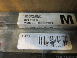
Hi. I own a 2000 C5. I get the 28 TCS - C1255 H - EBTCM Internal Malfunction. I have a Delphi D Model 09356961 with a Large M on it. My traction control and ABS light is on. Trying to find out if my module can be repaired because you need a wheel barrel full of money to replace it. It seems that the early C5's have the more expensive fixes than the 01 - 04's. Anybody out there have a good lead as to where I can start looking.
Navigation
Install the app
How to install the app on iOS
Follow along with the video below to see how to install our site as a web app on your home screen.
Note: This feature may not be available in some browsers.
More options
Style variation
You are using an out of date browser. It may not display this or other websites correctly.
You should upgrade or use an alternative browser.
You should upgrade or use an alternative browser.
EBTCM, Repair or Replace
- Thread starter JJVG
- Start date
R
RockyPM
There are resistors that fail and can be replaced. Saw it on Wheeler Dealer's program. Googled and found this from another website. Hope it helps and if you don't want to attempt it yourself, find a local shop or electronics repair to do it.
For 2001 and later C5's
First, if you don’t already know how, you’ll want to Pull Your Codes
Next, I will direct you to the Electrical Info Thread where you should try to take care of any issues you could have in the ground points. (Thanks to Bill Curlee for the thread)
Once the grounds have been cleaned and taken care of we’ll move on to the removal of the EBCM. I'm aware that step 7 says to send it to ABSfixer. Disregard that step and we'll proceed to the disassembly of the EBCM.
Items required:
Soldering Iron
Solder
De-Solder braid or pump
1 Phillips Screw Driver
Exacto Knife
Tube of Silicone Sealent
Now in order to remove the case I followed these steps:
1. remove 4 x screws
2. remove silicon from that hole on the back lower corner of the EBCM.
3. use a 2BA (or similar) 'thread tap' to cut a thread in that hole
4. screw matching thread screw/bolt into hole, (it misses pcb inside) until it touches cover plate (screw/bolt needs to be 3" long max).
5. carry on winding the screw in until it starts pushing the cover plate away enough to break that gasket seal and allow space to insert those flat blade screwdrivers and work around the remainder. (Thank You JerseyC5)
But if you’re like me you won’t have a tap to make a nice threaded hole. I was lucky and found a screw long enough and small enough to be threaded by hand. This is used to apply enough pressure so the back would separate. Refer to the image and said screw I used:
[IMG alt="Name: DSCN0070.jpg
Views: 18221
Size: 23.8 KB"]https://www.corvetteforum.com/forum...hrough-absfixer-or-fleabay-dscn0070.jpg[/IMG]
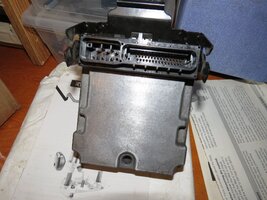
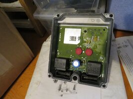
Once the EBCM is taken apart it will look this (Once again Thank You Bill Curlee):
[IMG alt="Name: C5EBTCMdisassembled9.jpg
Views: 17962
Size: 169.5 KB"]https://www.corvetteforum.com/forum...xer-or-fleabay-c5ebtcmdisassembled9.jpg[/IMG]
[IMG alt="Name: C5EBTCMdisassembled13.jpg
Views: 18549
Size: 182.7 KB"]https://www.corvetteforum.com/forum...er-or-fleabay-c5ebtcmdisassembled13.jpg[/IMG]
[IMG alt="Name: C5EBTCMdisassembled6.jpg
Views: 17840
Size: 100.7 KB"]https://www.corvetteforum.com/forum...xer-or-fleabay-c5ebtcmdisassembled6.jpg[/IMG]
[IMG alt="Name: C5EBTCMdisassembled1.jpg
Views: 17505
Size: 167.9 KB"]https://www.corvetteforum.com/forum...xer-or-fleabay-c5ebtcmdisassembled1.jpg[/IMG]
[IMG alt="Name: C5EBTCMdisassembled12.jpg
Views: 17843
Size: 120.1 KB"]https://www.corvetteforum.com/forum...er-or-fleabay-c5ebtcmdisassembled12.jpg[/IMG]
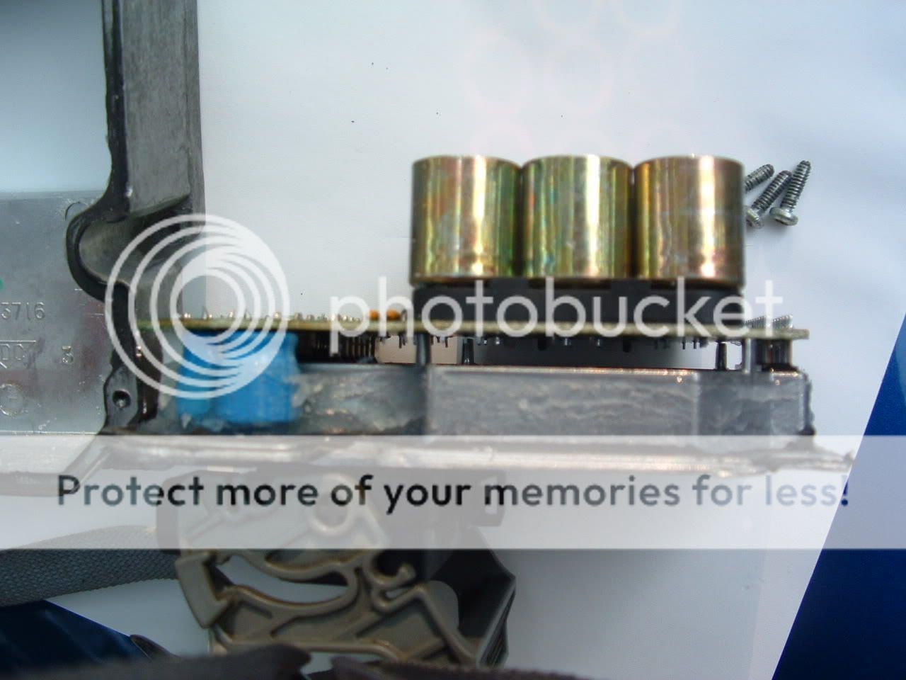
You may need some good lighting and possibly a magnifying glass to inspect the solder points of 5posts.
[IMG alt="Name: 6622041b.jpg
Views: 17878
Size: 43.0 KB"]https://www.corvetteforum.com/forum...hrough-absfixer-or-fleabay-6622041b.jpg[/IMG]
This most likely, as with so many others on the Forum causing the C1214 code. You need to get a soldering iron and some solder to re-solder any point that looks questionable. Once done you will want to test the EBCM, so put the box back together WITHOUT sealant and temp install the EBCM in your C5. Clear any codes before starting your car and you should be ok to start her up and check for any DIC messages.
If you have no messages then you've successfully repaired your own EBCM. Remove the EBCM apply some silicone and put the box back together completely. Install the EBCM using the steps here in reverse.
For replacing relay
If you suspect or may want to buy a new relay as a “just in case,” you’ll need to Go HEREand place an order for a new relay (The relay PB1321-ND HAS BEEN SUPERCEDED BY N000ORWH-SH-112D, N000 & the link is current with this info). You’ll also need to remove the silicone that’s surrounding the relay like so
[IMG alt="Name: DSCN0077.jpg
Views: 17406
Size: 43.7 KB"]https://www.corvetteforum.com/forum...hrough-absfixer-or-fleabay-dscn0077.jpg[/IMG]
[IMG alt="Name: DSCN0078.jpg
Views: 17225
Size: 45.7 KB"]https://www.corvetteforum.com/forum...hrough-absfixer-or-fleabay-dscn0078.jpg[/IMG]
Be very careful to not cut anything around the relay or the Circuit Board. Once the silicone is removed de-solder the points and cut a small amount off of each post in order to lower the relay and slide it out.
Take the new relay and just like the relay you removed, you may have to cut some material off each post to get it to fit. Install the relay, solder the points and refer to the instructions for install above.
Hopefully this makes enough sense for you guys to follow. Again if you have any questions feel free to ask.
Thanks to everyone who helped me and to the members who had previous info on this stupid C1214 code.
nvusgt
For 2001 and later C5's
First, if you don’t already know how, you’ll want to Pull Your Codes
Next, I will direct you to the Electrical Info Thread where you should try to take care of any issues you could have in the ground points. (Thanks to Bill Curlee for the thread)
Once the grounds have been cleaned and taken care of we’ll move on to the removal of the EBCM. I'm aware that step 7 says to send it to ABSfixer. Disregard that step and we'll proceed to the disassembly of the EBCM.
Items required:
Soldering Iron
Solder
De-Solder braid or pump
1 Phillips Screw Driver
Exacto Knife
Tube of Silicone Sealent
Now in order to remove the case I followed these steps:
1. remove 4 x screws
2. remove silicon from that hole on the back lower corner of the EBCM.
3. use a 2BA (or similar) 'thread tap' to cut a thread in that hole
4. screw matching thread screw/bolt into hole, (it misses pcb inside) until it touches cover plate (screw/bolt needs to be 3" long max).
5. carry on winding the screw in until it starts pushing the cover plate away enough to break that gasket seal and allow space to insert those flat blade screwdrivers and work around the remainder. (Thank You JerseyC5)
But if you’re like me you won’t have a tap to make a nice threaded hole. I was lucky and found a screw long enough and small enough to be threaded by hand. This is used to apply enough pressure so the back would separate. Refer to the image and said screw I used:
[IMG alt="Name: DSCN0070.jpg
Views: 18221
Size: 23.8 KB"]https://www.corvetteforum.com/forum...hrough-absfixer-or-fleabay-dscn0070.jpg[/IMG]
Once the EBCM is taken apart it will look this (Once again Thank You Bill Curlee):
[IMG alt="Name: C5EBTCMdisassembled9.jpg
Views: 17962
Size: 169.5 KB"]https://www.corvetteforum.com/forum...xer-or-fleabay-c5ebtcmdisassembled9.jpg[/IMG]
[IMG alt="Name: C5EBTCMdisassembled13.jpg
Views: 18549
Size: 182.7 KB"]https://www.corvetteforum.com/forum...er-or-fleabay-c5ebtcmdisassembled13.jpg[/IMG]
[IMG alt="Name: C5EBTCMdisassembled6.jpg
Views: 17840
Size: 100.7 KB"]https://www.corvetteforum.com/forum...xer-or-fleabay-c5ebtcmdisassembled6.jpg[/IMG]
[IMG alt="Name: C5EBTCMdisassembled1.jpg
Views: 17505
Size: 167.9 KB"]https://www.corvetteforum.com/forum...xer-or-fleabay-c5ebtcmdisassembled1.jpg[/IMG]
[IMG alt="Name: C5EBTCMdisassembled12.jpg
Views: 17843
Size: 120.1 KB"]https://www.corvetteforum.com/forum...er-or-fleabay-c5ebtcmdisassembled12.jpg[/IMG]
You may need some good lighting and possibly a magnifying glass to inspect the solder points of 5posts.
[IMG alt="Name: 6622041b.jpg
Views: 17878
Size: 43.0 KB"]https://www.corvetteforum.com/forum...hrough-absfixer-or-fleabay-6622041b.jpg[/IMG]
This most likely, as with so many others on the Forum causing the C1214 code. You need to get a soldering iron and some solder to re-solder any point that looks questionable. Once done you will want to test the EBCM, so put the box back together WITHOUT sealant and temp install the EBCM in your C5. Clear any codes before starting your car and you should be ok to start her up and check for any DIC messages.
If you have no messages then you've successfully repaired your own EBCM. Remove the EBCM apply some silicone and put the box back together completely. Install the EBCM using the steps here in reverse.
For replacing relay
If you suspect or may want to buy a new relay as a “just in case,” you’ll need to Go HEREand place an order for a new relay (The relay PB1321-ND HAS BEEN SUPERCEDED BY N000ORWH-SH-112D, N000 & the link is current with this info). You’ll also need to remove the silicone that’s surrounding the relay like so
[IMG alt="Name: DSCN0077.jpg
Views: 17406
Size: 43.7 KB"]https://www.corvetteforum.com/forum...hrough-absfixer-or-fleabay-dscn0077.jpg[/IMG]
[IMG alt="Name: DSCN0078.jpg
Views: 17225
Size: 45.7 KB"]https://www.corvetteforum.com/forum...hrough-absfixer-or-fleabay-dscn0078.jpg[/IMG]
Be very careful to not cut anything around the relay or the Circuit Board. Once the silicone is removed de-solder the points and cut a small amount off of each post in order to lower the relay and slide it out.
Take the new relay and just like the relay you removed, you may have to cut some material off each post to get it to fit. Install the relay, solder the points and refer to the instructions for install above.
Hopefully this makes enough sense for you guys to follow. Again if you have any questions feel free to ask.
Thanks to everyone who helped me and to the members who had previous info on this stupid C1214 code.
nvusgt
As he mentioned this procedure is only applicable on 2001 to 2004. 2000 C5 like mine, we’re in trouble as these modules are no longer available or will be made available by the manufacturer (bouche) if I’m not mistaken. I am aware that my 2000 C5 will not perform the same as when ABS and Traction Control are present. However, the car is still manageable at this stage for the past three years. Just being careful of the road condition. Will be going to US when all these COVID eased up. Somewhere in MO is a place where they refurbished these modules. I hate to send mine now for the simple reason, what if they don’t send it back. As I said the car is still drivable. Will keep you posted of any development good or bad.There are resistors that fail and can be replaced. Saw it on Wheeler Dealer's program. Googled and found this from another website. Hope it helps and if you don't want to attempt it yourself, find a local shop or electronics repair to do it.
For 2001 and later C5's
First, if you don’t already know how, you’ll want to Pull Your Codes
Next, I will direct you to the Electrical Info Thread where you should try to take care of any issues you could have in the ground points. (Thanks to Bill Curlee for the thread)
Once the grounds have been cleaned and taken care of we’ll move on to the removal of the EBCM. I'm aware that step 7 says to send it to ABSfixer. Disregard that step and we'll proceed to the disassembly of the EBCM.
Items required:
Soldering Iron
Solder
De-Solder braid or pump
1 Phillips Screw Driver
Exacto Knife
Tube of Silicone Sealent
Now in order to remove the case I followed these steps:
1. remove 4 x screws
2. remove silicon from that hole on the back lower corner of the EBCM.
3. use a 2BA (or similar) 'thread tap' to cut a thread in that hole
4. screw matching thread screw/bolt into hole, (it misses pcb inside) until it touches cover plate (screw/bolt needs to be 3" long max).
5. carry on winding the screw in until it starts pushing the cover plate away enough to break that gasket seal and allow space to insert those flat blade screwdrivers and work around the remainder. (Thank You JerseyC5)
But if you’re like me you won’t have a tap to make a nice threaded hole. I was lucky and found a screw long enough and small enough to be threaded by hand. This is used to apply enough pressure so the back would separate. Refer to the image and said screw I used:
[IMG alt="Name: DSCN0070.jpg
Views: 18221
Size: 23.8 KB"]https://www.corvetteforum.com/forum...hrough-absfixer-or-fleabay-dscn0070.jpg[/IMG]
Once the EBCM is taken apart it will look this (Once again Thank You Bill Curlee):
[IMG alt="Name: C5EBTCMdisassembled9.jpg
Views: 17962
Size: 169.5 KB"]https://www.corvetteforum.com/forum...xer-or-fleabay-c5ebtcmdisassembled9.jpg[/IMG]
[IMG alt="Name: C5EBTCMdisassembled13.jpg
Views: 18549
Size: 182.7 KB"]https://www.corvetteforum.com/forum...er-or-fleabay-c5ebtcmdisassembled13.jpg[/IMG]
[IMG alt="Name: C5EBTCMdisassembled6.jpg
Views: 17840
Size: 100.7 KB"]https://www.corvetteforum.com/forum...xer-or-fleabay-c5ebtcmdisassembled6.jpg[/IMG]
[IMG alt="Name: C5EBTCMdisassembled1.jpg
Views: 17505
Size: 167.9 KB"]https://www.corvetteforum.com/forum...xer-or-fleabay-c5ebtcmdisassembled1.jpg[/IMG]
[IMG alt="Name: C5EBTCMdisassembled12.jpg
Views: 17843
Size: 120.1 KB"]https://www.corvetteforum.com/forum...er-or-fleabay-c5ebtcmdisassembled12.jpg[/IMG]
You may need some good lighting and possibly a magnifying glass to inspect the solder points of 5posts.
[IMG alt="Name: 6622041b.jpg
Views: 17878
Size: 43.0 KB"]https://www.corvetteforum.com/forum...hrough-absfixer-or-fleabay-6622041b.jpg[/IMG]
This most likely, as with so many others on the Forum causing the C1214 code. You need to get a soldering iron and some solder to re-solder any point that looks questionable. Once done you will want to test the EBCM, so put the box back together WITHOUT sealant and temp install the EBCM in your C5. Clear any codes before starting your car and you should be ok to start her up and check for any DIC messages.
If you have no messages then you've successfully repaired your own EBCM. Remove the EBCM apply some silicone and put the box back together completely. Install the EBCM using the steps here in reverse.
For replacing relay
If you suspect or may want to buy a new relay as a “just in case,” you’ll need to Go HEREand place an order for a new relay (The relay PB1321-ND HAS BEEN SUPERCEDED BY N000ORWH-SH-112D, N000 & the link is current with this info). You’ll also need to remove the silicone that’s surrounding the relay like so
[IMG alt="Name: DSCN0077.jpg
Views: 17406
Size: 43.7 KB"]https://www.corvetteforum.com/forum...hrough-absfixer-or-fleabay-dscn0077.jpg[/IMG]
[IMG alt="Name: DSCN0078.jpg
Views: 17225
Size: 45.7 KB"]https://www.corvetteforum.com/forum...hrough-absfixer-or-fleabay-dscn0078.jpg[/IMG]
Be very careful to not cut anything around the relay or the Circuit Board. Once the silicone is removed de-solder the points and cut a small amount off of each post in order to lower the relay and slide it out.
Take the new relay and just like the relay you removed, you may have to cut some material off each post to get it to fit. Install the relay, solder the points and refer to the instructions for install above.
Hopefully this makes enough sense for you guys to follow. Again if you have any questions feel free to ask.
Thanks to everyone who helped me and to the members who had previous info on this stupid C1214 code.
nvusgt
Attachments

As he mentioned this procedure is only applicable on 2001 to 2004. 2000 C5 like mine, we’re in trouble as these modules are no longer available or will be made available by the manufacturer (bouche) if I’m not mistaken. I am aware that my 2000 C5 will not perform the same as when ABS and Traction Control are present. However, the car is still manageable at this stage for the past three years. Just being careful of the road condition. Will be going to US when all these COVID eased up. Somewhere in MO is a place where they refurbished these modules. I hate to send mine now for the simple reason, what if they don’t send it back. As I said the car is still drivable. Will keep you posted of any development good or bad.
Any place where you could find one out of a scrapped 2000 for cheap? Maybe you could send that one away to be repaired and you still will have your original just in case it doesn't get back to you.
- Thread starter
- #5
I've seen the fix it procedure done on you tube by several different guys at different levels of ability and they all fixed the issue. Like 2kforever C5 says, I have a 2000 model year and the only fix is a wad of money for a used one. Some guy on eBay is selling a used one for $1900.00 plus shipping etc. Still searching. Thanks for your info.
I've seen the fix it procedure done on you tube by several different guys at different levels of ability and they all fixed the issue. Like 2kforever C5 says, I have a 2000 model year and the only fix is a wad of money for a used one. Some guy on eBay is selling a used one for $1900.00 plus shipping etc. Still searching. Thanks for your info.
Yes I hear you. Our module ‘99 and 2000 have a different module from 2001 to 2004. So far the best C5 that I would like change to would be the 2003.I've seen the fix it procedure done on you tube by several different guys at different levels of ability and they all fixed the issue. Like 2kforever C5 says, I have a 2000 model year and the only fix is a wad of money for a used one. Some guy on eBay is selling a used one for $1900.00 plus shipping etc. Still searching. Thanks for your info.


- Thread starter
- #7
I hear that. After owning this one for a year & a half and trying to fix different projects on the car especially relating to electronics, I wish I had waited and bought a later C5 model.
Well maybe we might get a chance yet for a 2003.I hear that. After owning this one for a year & a half and trying to fix different projects on the car especially relating to electronics, I wish I had waited and bought a later C5 model.

The EBCM repair is definitely a problem with C5s. I have a 2003 coupe 6 speed and had this problem with mine a couple of years ago. I had it repaired here in North Toronto. The company that repairs electronics on all kinds of vehicles is BBA Reman. They have repair centre's all over the world including several across Canada. Their website is bba-reman.com and they are located at 467 Edgeley Blvd, Concord, Ontario here in the Toronto area. It cost me $250.00 and they guarantee the repair for as long as you own the car. Mine has been working perfectly ever since the repair.
Good luck. By the way you can still drive your car with the module removed you just don't have any traction control, stability control or ABS. Just like old school.
Good luck. By the way you can still drive your car with the module removed you just don't have any traction control, stability control or ABS. Just like old school.
Yes I hear you. The EBCM on a 2003 C5 is completely different. It’s actually an easy fix if I had your kinda module. You have the best C5 production. Treasure that one. Thanks for the website. Will send them my module when summer is over. They can work on it over the winter. Likewise, removal is not that easy but manageable.The EBCM repair is definitely a problem with C5s. I have a 2003 coupe 6 speed and had this problem with mine a couple of years ago. I had it repaired here in North Toronto. The company that repairs electronics on all kinds of vehicles is BBA Reman. They have repair centre's all over the world including several across Canada. Their website is bba-reman.com and they are located at 467 Edgeley Blvd, Concord, Ontario here in the Toronto area. It cost me $250.00 and they guarantee the repair for as long as you own the car. Mine has been working perfectly ever since the repair.
Good luck. By the way you can still drive your car with the module removed you just don't have any traction control, stability control

- Thread starter
- #11
I found a website called thecorvettemechanic.com under the forum he shows a fix that was done on a 2000 C5 EBCM. But he says that it only fixes 2 codes and it's for the module with the Capital V on it for active handling. The codes it fixes are C1214 & C1218. Check it out, might help somebody out there. Scroll down just past halfway on his page and look for the big lettering.
Trying the website. Cannot Locate. Do you have a phone number I can call? Preferably a cellphone. My number isYes I hear you. The EBCM on a 2003 C5 is completely different. It’s actually an easy fix if I had your kinda module. You have the best C5 production. Treasure that one. Thanks for the website. Will send them my module when summer is over. They can work on it over the winter. Likewise, removal is not that easy but manageable.
780 709 1564 (Edmonton, AB) Avelino
Email. avelmadlans@yahoo .ca
Greatly appreciate if you can help please Thanks
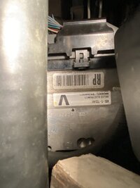
That's exactly what I have. ABS-5-TCS/AH VI found a website called thecorvettemechanic.com under the forum he shows a fix that was done on a 2000 C5 EBCM. But he says that it only fixes 2 codes and it's for the module with the Capital V on it for active handling. The codes it fixes are C1214 & C1218. Check it out, might help somebody out there. Scroll down just past halfway on his page and look for the big lettering.
DELCO ELECTRONICS
MODEL - 09360921
Will be checking their website Thank you - thank you - thank you
Tried that website but cannot locate. You happen to have a phone number I can call? Preferably a cell number. ThanksThat's exactly what I have. ABS-5-TCS/AH V
DELCO ELECTRONICS
MODEL - 09360921
Will be checking their website Thank you - thank you - thank you
If you can give him my Cellphone number 780 709 1564Tried that website but cannot locate. You happen to have a phone number I can call? Preferably a cell number. Thanks
or email to [email protected]
Edmonton, AB
Thanks
- Thread starter
- #16
This is how I found it. On google "Image search" Type, The Corvette Mechanic ABS. scroll down until you see a pic of the inside of an EBCM. Click on it and then click on it again in the side window. When there scroll down until you see the large print.


Im NEW here. Where can I send my MODULE to get fixed in Canada?This is how I found it. On google "Image search" Type, The Corvette Mechanic ABS. scroll down until you see a pic of the inside of an EBCM. Click on it and then click on it again in the side window. When there scroll down until you see the large print.View attachment 80838View attachment 80839View attachment 80840View attachment 80841View attachment 80842
2000 coupe 6 speed. (Model 09360921)
- Thread starter
- #18
That's what I'd like to know? I'm currently replacing my ac compressor the condenser the dryer and orifice. So I decided it was a good time to address the EBCM and put in a new thermostat. Both these jobs show why you should buy a C5 2001 or later. The EBCM is impossible to replace. If you find one they want a huge wad of cash for it. You can't replace just the thermostat. You have to replace the housing as well, they are two parts but sell as 1 unit. Don't get me started on the key FOB's. Oh well such is the life of getting an affordable Vette. Your going to pay, either up front or down the road. Well I'm looking forward to getting this car on it's wheels again hopefully by summer.
Patience my friend. There’s light at the end of the tunnel.That's what I'd like to know? I'm currently replacing my ac compressor the condenser the dryer and orifice. So I decided it was a good time to address the EBCM and put in a new thermostat. Both these jobs show why you should buy a C5 2001 or later. The EBCM is impossible to replace. If you find one they want a huge wad of cash for it. You can't replace just the thermostat. You have to replace the housing as well, they are two parts but sell as 1 unit. Don't get me started on the key FOB's. Oh well such is the life of getting an affordable Vette. Your going to pay, either up front or down the road. Well I'm looking forward to getting this car on it's wheels again hopefully by summer.
I'm not giving up on my 2000 C5 even with the ABS / Traction Control issue. I'm confident that I'll get this issue rectified one of these days.Patience my friend. There’s light at the end of the tunnel.
Users who are viewing this thread
Total: 1 (members: 0, guests: 1)